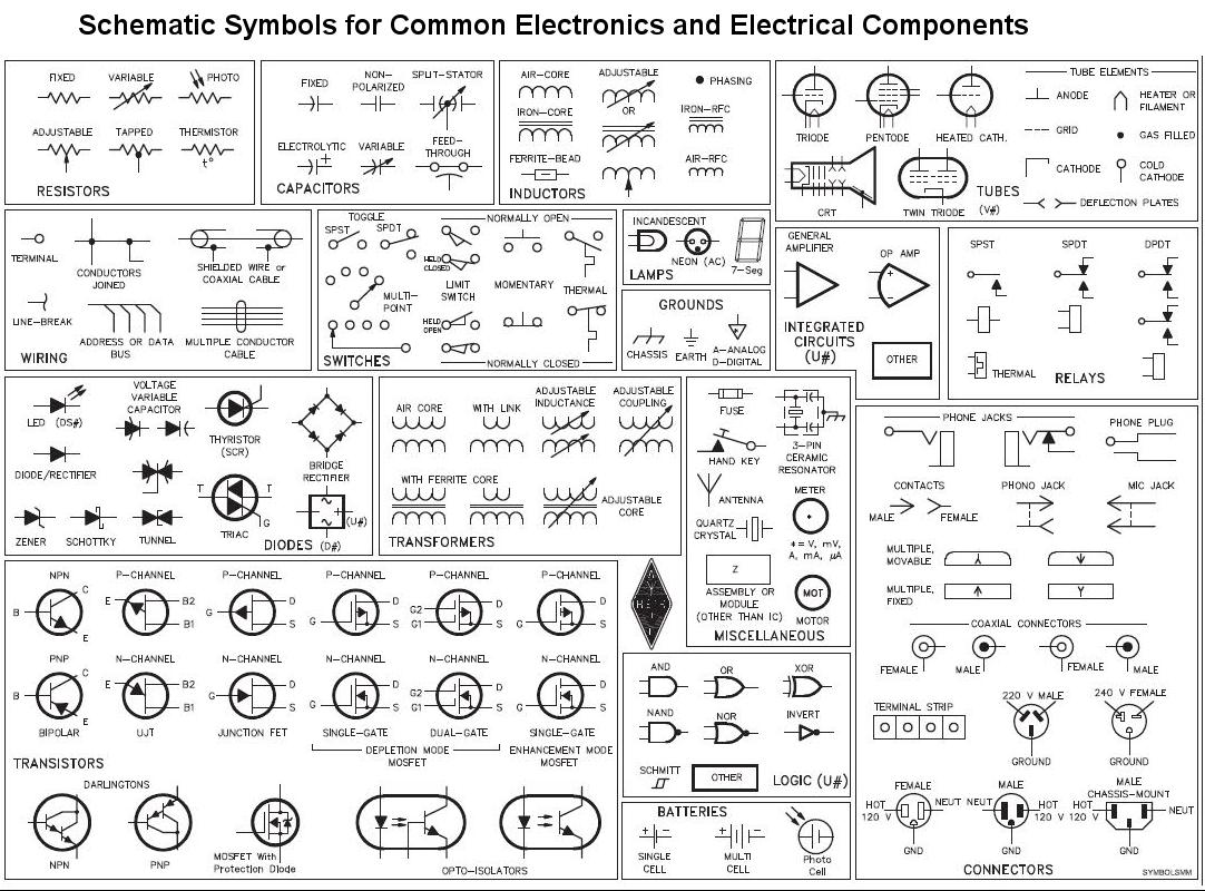
Electronics Symbols Chart

Electronics symbols chart
10 common electrical symbols found on electrical schematic...
<ul class="i8Z77e"><li class="TrT0Xe">Phase Meter.</li><li class="TrT0Xe">240V Outlet.</li><li class="TrT0Xe">Flow Switch.</li><li class="TrT0Xe">NOR Gate.</li><li class="TrT0Xe">Continuously Adjustable Resistor.</li><li class="TrT0Xe">Normally open foot switch.</li><li class="TrT0Xe">Timer off delay, normally open.</li><li class="TrT0Xe">Shielded transformer with magnetic core.</li></ul>What do electronic symbols mean?
Electrical symbols are a graphical representation of basic electrical and electronic devices or components. These Symbols are used in circuit and electrical diagrams to recognize a component. It is also called a schematic symbol. Each component has typical functionality according to its operational characteristics.
What are the symbols used in electrical?
| Name | Description |
|---|---|
| Electrical Wire | It is the symbol that is used to represent a wire. |
| Connected Wires | This Symbol represents the wire connected crossing. |
| Not Connect Wires | This Symbol shows that wires are not connected on crossing. |
What are the most common circuit symbols?
Below is an overview of the most used symbols in circuit diagrams.
- Battery. The symbol for a battery is shown below.
- Resistor. The schematic symbol of the resistor are drawn in two different ways. ...
- Potentiometer. ...
- Schematic Symbols of a Transistor. ...
- Schematic Symbol for an Integrated Circuit. ...
- Logic Gates. ...
- Inductor. ...
- Transformer.
What are the 6 common electrical terms?
6 Electrical Terms You Should Know
- Circuit. A circuit, in the electrical sense, is a system connected by electrical wires.
- Surge. Electrical current is normally controlled, but sometimes extra voltage flows through and causes a surge. ...
- Breaker. ...
- Wattage. ...
- Lumens. ...
- Grounding.
What are the voltage symbols?
Voltage
- “V” with a wavy line over it = AC voltage.
- “V” with one dotted and one solid over it = DC voltage.
- “mV” with one wavy line or a pair of lines, one dotted and one solid, over it = AC or DC millivolts.
How do you read electrical symbols?
Page to have a quick look at the symbols. You see a three-phase ac electric motor symbol. Here this
How do you read circuit symbols?
In North America the symbol for the resistor is a zigzag line like this the international standard
What are the 5 types of wiring diagram?
6.2: Types of Electrical Diagrams
- Schematic Diagrams.
- Wiring diagrams.
- Block diagrams.
- Pictorial diagrams.
What is a resistor symbol?
The ohm (symbol: Ω) is the SI unit of electrical resistance, named after Georg Simon Ohm. An ohm is equivalent to a volt per ampere.
What is the symbol for current?
Current is usually denoted by the symbol I. Ohm's law relates the current flowing through a conductor to the voltage V and resistance R; that is, V = IR.
What is a diode in a circuit?
A diode is a semiconductor device that essentially acts as a one-way switch for current. It allows current to flow easily in one direction, but severely restricts current from flowing in the opposite direction.
What are the 3 major circuits?
The three major circuits of blood flow in the body are the systemic, cerebral, and pulmonary circuits.
What does Z mean on a circuit board?
X: crystal, ceramic resonator. XMER: transformer. XTAL: crystal. Z: zener diode.
What is the capacitor symbol?
The curved plate represents the cathode (negative) of the capacitor, and the other plate is anode (positive). Sometimes a plus sign is also added to the positive side. The SI unit of capacitance is farad (Symbol: F).
What are the 5 main circuits?
Types of Electric Circuit- Closed circuits, open circuits, short circuits, series circuits, and parallel circuits are the five main types of electric circuits.
What are the 7 types of electricity?
Electricity takes different forms: coal, water, solar, wind, nuclear, hydro and solar.
What are the 4 basic electrical circuits?
The main types of electric circuits are Close Circuit, Open Circuit, Short Circuit, Series Circuit, and Parallel Circuit. Electric circuit provides the conductive path for the flow of electric charge or electric current.
Are houses AC or DC?
When you plug things into the outlet in your house, you don't get DC. Household outlets are AC - Alternating Current. This current has a frequency of 60 Hz and would look something like this (if you plotted current as a function of time).
How do I know if a wire is AC or DC?
In direct current (DC), the electric charge (current) only flows in one direction. Electric charge in alternating current (AC), on the other hand, changes direction periodically. The voltage in AC circuits also periodically reverses because the current changes direction.
10 Electronics symbols chart Images
August 2014 Electrical Engineering Pics Electronics basics

Basic Power Electronics Symbols Chart

Basic electroins Electronic schematics Electronics circuit

Pin on Home electrical wiring
Electronics on Pinterest Arduino Electrical Engineering and Led

Image result for electronic symbols and names Electronics components

Pin by Edgefx Kits on Knowledge Electronics components Electronics

Easy to read schematics all Electronics symbols Basic Basic

Introduction to Basic Electronics Electronic Components and Projects
Post a Comment for "Electronics Symbols Chart"